[ Chris Fallin ]
Disclaimer: Halogen lights get very hot and can produce harmful ultraviolet radiation if not shielded correctly. In addition, though this system is low voltage and no direct shock hazard exists at 12 volts, the currents are very high and extreme care should be taken around a live system. I bear no responsibility for injury to person or property as a result of anything that this inspires. Be smart, be careful!
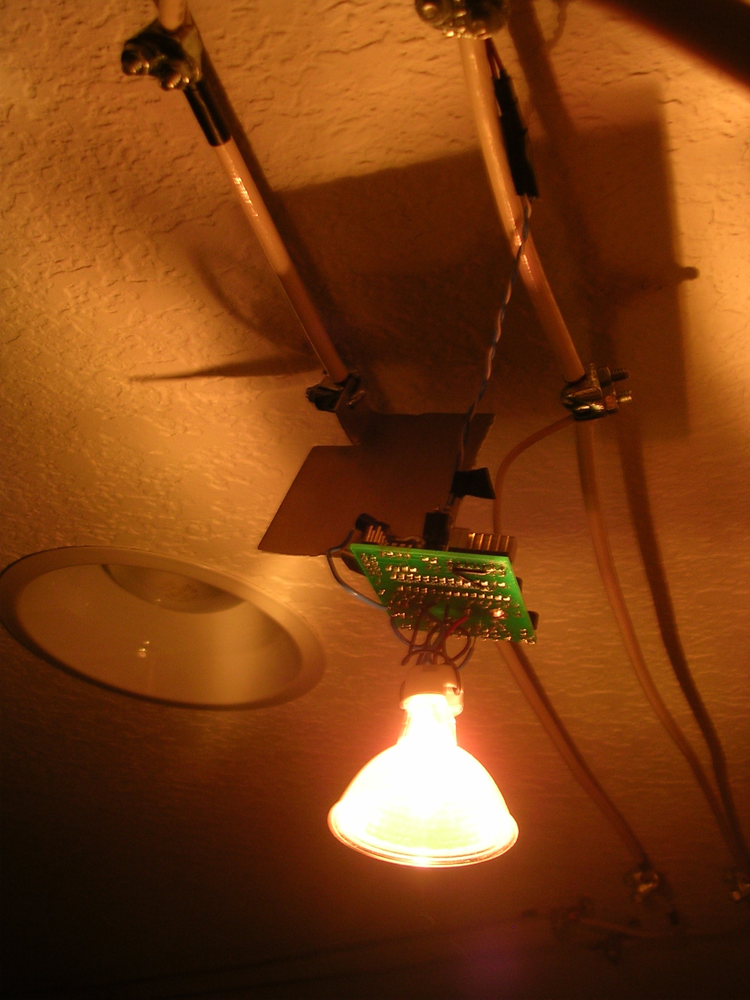
digilight is an Atmel AVR microcontroller-based project consisting of several dimmer modules, each with one 12 volt, 50 watt halogen lamp, controlled by a shared serial data bus carrying the DMX-512 lighting control protocol.
Due to lack of time, only one lighting module was ever constructed. The transformer box was designed to power 10 modules (500 watts total power), however, and 10 PCBs were manufactured. Perhaps someday I'll get around to building the remaining modules. As it happens, the system is currently installed on my bedroom ceiling at my parents' house and, since starting the project, I've gone away to college. The project is presented here despite its inactive/incomplete state.
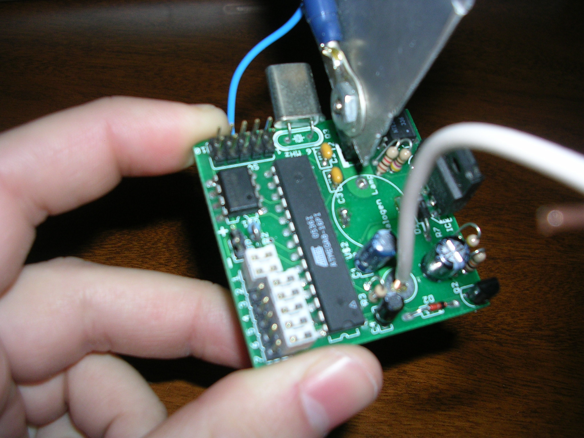
Board close-up
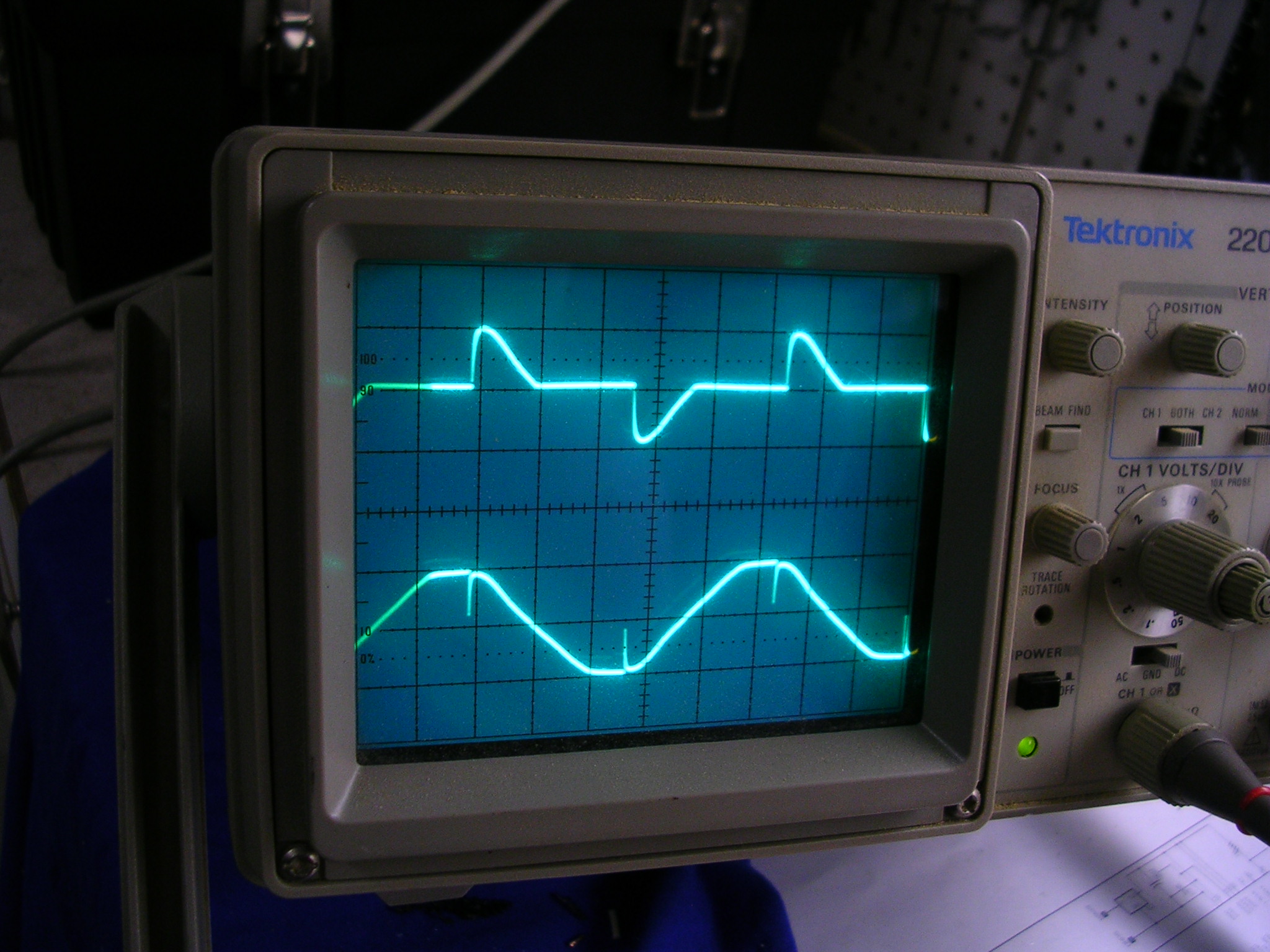
Chopped AC waveform (top channel)
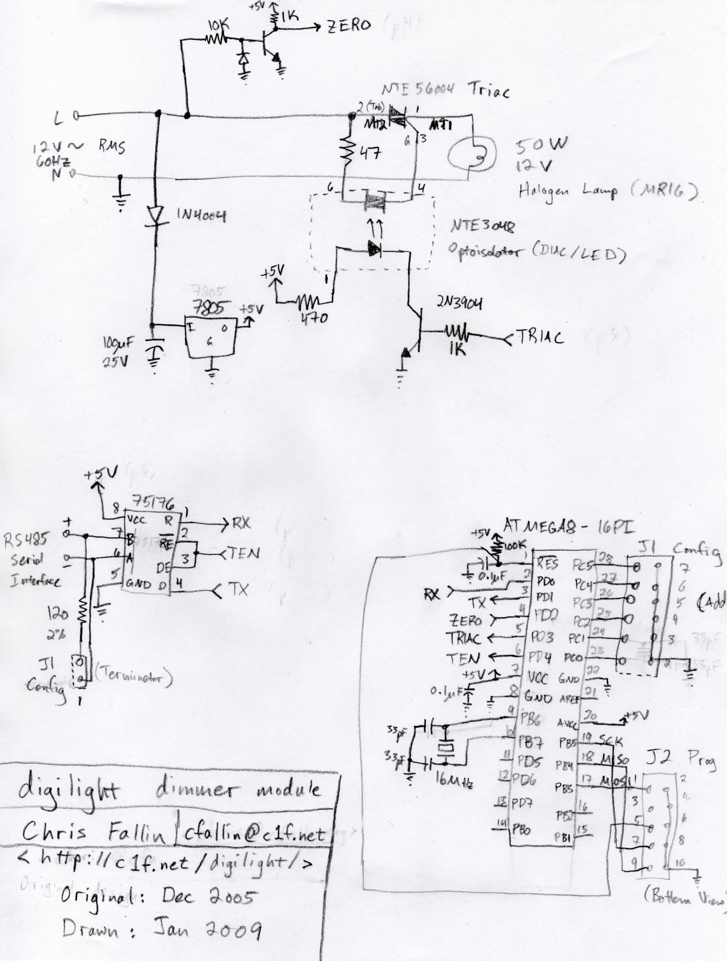
Rough schematic
A rough schematic is given below, at left. Regretfully, the original schematics and the board layout files are lost. This schematic was reverse-engineered from the board.
Each dimmer module is a self-sufficient system, built around an Atmel ATmega8 microcontroller. This platform is unique (and highly fun!) in several ways, among them a GCC port for the architecture. The chip itself needs very little: 5V power, an external crystal (since we're doing serial communication, we need an accurate timebase), and an RC reset circuit. It has several builtin peripherals that make this application especially straightforward: a UART, several internal timers, and external interrupt functionality.
A few notes on AC dimming before we proceed. The standard method of dimming an incandescent light -- implemented by 120V dimmer switches everywhere -- is to turn the lamp on for only a part of each AC half-cycle. A device called a triac -- a high-current silicon switching device -- blocks current by default, but can be triggered into conduction by a small current on its gate, and will continue to conduct until the load current reaches zero (at the AC zero crossing, for a resistive load). All one needs to do, then, is to trigger the triac partway through each half-cycle; the later the trigger, the lower the average power, and the dimmer the lamp.
The AVR has one input and one output that control dimming. The input comes from a single-transistor level converter that gives a logic low when the AC waveform is in the positive half-cycle and a logic high otherwise. When this input line is configured as an edge-sensitive interrupt, the firmware can synchronize to the AC zero crossings. The output drives an optoisolator (via a transistor buffer) that triggers the triac.
The AVR receives control data via the DMX-512 protocol, which uses the RS-485 electrical standard. This is a differential transmission line; we need not concern over the details, except that the SN75176A transceiver chip conveniently level-converts from RS-485 to TTL. We interface this directly with the AVR's UART RX/TX pins. The hardware is capable of transmitting as well as receiving; however, the firmware currently does not make use of this feature (extensions to DMX-512 allow bidirectional communication but the original spec assumes "dumb" dimmers that receive a continuous stream of data).
Finally, power is provided off the 12V AC line by a simple half-wave rectifier and a 7805 voltage regulator.
As an implementation note, the triac is a connected-tab type, and the tab is the terminal that receives power from the line. I used a flat-plate heatsink (homemade) bolted to the tab, and the heatsink doubled as the attachment point to the power cabling. This worked out nicely: the entire module hangs from the parallel cables, and so I merely had to drill a hole in the plate to pass the U-hook that bolts onto the cable.
The in-circuit programming header uses the standard 10-pin programming pinout, and can be attached to a parallel port using a circuit like this one.
View online: dimmer/. Download: dimmer.tar.gz.
The firmware is written in C and compiles with AVR-GCC. The Makefile has a rule to program the chip using uisp (set to use the parallel port dongle linked above), available on Linux and Windows. Note that the fuses must be set appropriately for the external crystal oscillator -- there is a separate Makefile rule for that.
Using the right hardware peripherals, the firmware is trivial. The system is entirely interrupt-driven, such that the main loop is empty (conceivably, the micro could handle other tasks such as UI interfacing if the module were expanded into a larger integrated system).
The DMX code receives the DMX-512 protocol using the standard UART -- this is possible because we have selected a 16 MHz crystal and the 250kbps rate of DMX-512 can be produced exactly with a divisor of 64. The protocol uses one start bit and two stop bits, with 8 data bits, and the long start-of-packet bit will be received as a framing error, allowing for easy packet synchronization. The code reads the assigned module address from the jumpers on board (pins PC0-PC5) and sets a global variable with the channel intensity when the appropriate value comes across the wire.
The dimming itself is incredibly simple. I use one internal timer, reset on every AC zero crossing, that in turn fires another interrupt to trigger the triac. Upon initialization, the code times one complete AC cycle (it is thus independent of AC mains frequency and system clock variances), and then builds a 256-entry lookup table that divides the cycle time into equal intervals. Then, on every zero crossing interrupt, I use this lookup table to determine how far into the cycle the triac should trigger; the timer limit is set to this count. On the timer interrupt, the triac line is asserted for 48 cycles (determined experimentally to be a reliable pulse length). Once these interrupts are enabled, the subsystem is free-running and its only interaction with the rest of the system is through the light-intensity global variable.
In October 2005, the fall of my senior year of high school, I was getting pretty bored, and I had an idea for a nifty project: a digitally controlled lighting system for my room. Some quick research turned up the standard method of dimming an incandescent lamp with a chopped AC waveform, using triac solid-state switching devices. I stocked up on AVR microcontrollers, bought some 12V, 50 watt halogen lamps and several cheap 12 volt transformers from a surplus shop, and got to work.
In December of 2005, I obtained a working prototype on a breadboard -- a single lamp controlled by an AVR ATmega16, tracking a potentiometer to set the brightness level. As luck would have it, I got pretty busy and did not return to the project until April 2006, when I built the first module on a 2 inch by 2 inch manufactured PCB. (My dad had done the PCB layout as a Christmas gift 4 months prior.) In August of that year, I moved away and began at Notre Dame -- in hindsight, the timing of the project right before college combined with its permanently-installed nature was not particularly smart. Nevertheless, two years later, in August 2008, I ressurrected the old prototype board, remounted it on the power-supply cables still on my ceiling, and then implemented the DMX reception routines, using a small known-good USB-DMX adapter (uDMX) I had previously built. I finally got around to documenting the thing in January 2009, three years after the epic (?) journey had begun.
As an addendum, I am making this very simplistic software available, based around the uDMX sample code, to drive the uDMX USB-DMX adapter. You will need libusb installed to compile this. The software comes in two parts: a daemon and a client. The daemon establishes a connection to the uDMX device and awaits connections on the local machine. The client is a simple ncurses-based console program that allows the levels of the first four channels to be adjusted. The reason for this split is twofold: first, establishing a connection to the uDMX is relatively slow and expensive, and second, the status of a light setup is long-term state that should be preserved between the operations of individual programs (such as manual lightboards, music-synchronized color organs, etc).
The client interface is very minimalistic. Read the source for the keybindings (I'm serious). Hey, I spent all my time playing with the microcontroller, you can't blame me for a rough host interface!
Comments, feedback, etc are appreciated! -- Chris Fallin 2009-01-04